
A router baseplate can look simple until the mounting screws miss by a fraction of an inch or the center opening interferes with a guide bushing. Knowing how to measure router baseplate dimensions before ordering prevents the most common fitment problems. Start with the router itself, not a product photo or a measurement taken from memory.
A replacement baseplate must match more than the overall shape. The mounting-hole pattern, screw type, center opening, and clearance around the router housing all matter. If your router has been modified, has an unusual subbase, or uses a nonstandard mounting arrangement, accurate measurements are the fastest route to the right plate or a custom order.
What You Need Before Measuring
Remove the router bit and unplug the router before handling the base. Set the tool upside down on a clean bench with the existing baseplate facing up. If dust, pitch, or finish residue covers the screw holes, clean it away so the edges are visible.
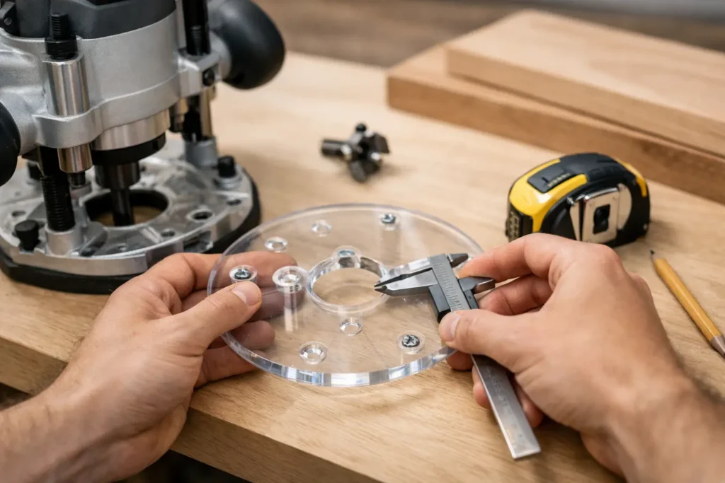
Use a steel rule for overall dimensions, but use calipers for hole diameters and more precise center-to-center measurements. A combination square is useful when you need to establish straight reference lines. Have a phone or camera nearby as well. Clear photos of the bottom of the router, including the screw holes and any molded features, can confirm details later.
For a complete fitment record, you will want these measurements:
- Overall outside diameter or outside width and length
- Center opening diameter
- Number of mounting holes
- Mounting-hole diameter and counterbore or countersink details
- Center-to-center distance between mounting holes
- Screw thread size, length, and head style
Measure the Existing Router Baseplate First
If the original baseplate is still installed and undamaged, it is your best reference. Measure its outside diameter if it is round. If it is rectangular, D-shaped, or has a flat edge, measure the widest length and width. Do not assume that two plates with the same outside diameter use the same mounting pattern.
Next, measure the center opening. This is the hole surrounding the collet and router bit. Measure the opening across its widest point. If your work uses template guides, guide bushings, or large panel-raising bits, this measurement deserves extra attention. A plate may mount correctly but still be the wrong choice if its opening is too small for your intended setup.
Check whether the center opening is actually centered in the plate. Most standard router bases are centered, but some specialty or offset plates are not. Measure from the edge of the center opening to several outside edges. If those distances differ, note the orientation of the plate relative to the router handles, switch, or cord.
Record the Shape and Any Clearance Features
Look beyond the basic diameter. Some router baseplates have notches, flats, handles, locating tabs, molded ribs, dust-port cutouts, or clearance areas around the motor housing. A clear plate with the correct screw pattern can still fail to sit flat if it contacts one of these features.
Trace the outside profile on paper if the shape is irregular. Mark the front of the router on the tracing. This is especially useful when the baseplate has a straight edge for guide work or when one portion extends farther than the rest of the plate.
How to Measure Router Baseplate Mounting Holes
Mounting holes determine compatibility. Count every hole in the existing baseplate, including holes that may have been used for an accessory rather than for attaching the plate. Then identify which holes actually attach the baseplate to the router housing.
Measure each mounting hole’s diameter with calipers. After that, inspect the top of the hole. A flat-bottom recess for a screw head is a counterbore. A tapered recess is a countersink. This distinction matters because the wrong screw-head style may sit proud of the plate and catch on a template or workpiece.
The most reliable way to measure hole spacing is center to center. With two holes, measure from the center of one hole to the center of the other. With three or four holes, measure all adjacent distances and, where practical, the distances across the pattern. Do not rely on one diagonal measurement alone.
If finding the exact center of a small hole is difficult, measure from the outside edge of one hole to the outside edge of the next hole when they are the same diameter. That measurement equals center-to-center spacing. If the holes differ in diameter, measure from one near edge to the other near edge and add half the diameter of each hole.
Use a Reference Point for Multi-Hole Patterns
For routers with three or more mounting holes, choose one hole as Hole A and work around the pattern clockwise. Write down the distances from Hole A to each remaining hole. Also note each hole’s position relative to the center opening.
This avoids a common mistake: a pattern can have matching distances but a different orientation. Two three-hole patterns may appear similar, yet one hole may be rotated several degrees from where it needs to be. A photo with the holes labeled A, B, C, and D is often more useful than measurements alone.
Check the Screws, Not Just the Holes
Remove one original mounting screw and keep it with your measurement notes. Measure the screw’s thread diameter, length from under the head to the tip, and head style. If you have a thread gauge, use it. If not, identify the router make and model and retain the original screw for comparison.
Do not replace a machine screw with a wood screw just because it seems to fit. Router baseplates mount into threaded metal inserts or tapped holes in the router housing. Incorrect threads can damage those holes. A screw that is too long can bottom out before clamping the plate, while one that is too short may not hold securely.
Also confirm whether the original plate uses washers. A washer can affect both screw length and the way the screw head sits in the counterbore. If a replacement plate has a different thickness than the original, the proper screw length may change.
Measure the Router Housing and Accessory Needs
A baseplate must clear the router body underneath, not just align at the screw locations. Measure the diameter of the mounting area on the router housing and the height of any raised rings, bosses, or locating features. If the router has a protruding depth-stop mechanism or a dust-collection attachment near the base, note its location.
Consider how you use the router. A small center opening may be adequate for edge profiling but unsuitable for guide bushings. A large opening improves bit clearance, yet it gives less material support close to the bit. An oversized plate can add stability on a broad surface, but it may be awkward when routing inside a narrow cabinet or close to a fence.
Plate thickness is another trade-off. A thicker baseplate is generally stiffer and more stable, particularly for larger plates used with jigs. However, it can reduce the available bit projection below the plate. Measure the original plate thickness and decide whether your planned work benefits more from added stiffness or maximum cutting depth.
Make a Fitment Note Before You Order
Put the measurements in one short record rather than relying on separate notes. Include the router manufacturer, exact model number, baseplate shape, outside dimensions, center opening, mounting-hole count, hole spacing, screw details, and any special clearance requirements. Add photos of the router bottom, the removed baseplate, and the original screws.
The router brand is a useful starting point, but the exact model is the deciding detail. Manufacturers may use different mounting patterns across models, even when the routers look similar. If you are selecting by router brand, confirm the listed model compatibility against your notes before placing the order.
When the pattern is unusual, the base has been modified, or you need a specialized opening or shape, provide the fitment record for a custom baseplate request. That gives the workshop the information needed to check the pattern instead of guessing from a general router description.
Recheck Before Final Installation
Before tightening anything, place the new baseplate against the router housing by hand. It should sit flat without rocking. Start all mounting screws loosely, then confirm the center opening is properly positioned around the collet. Tighten the screws gradually in an alternating pattern so the plate seats evenly.
With the router unplugged, rotate the bit by hand and check that it clears the opening. Then set the router on a known-flat surface to verify that no screw heads protrude below the plate. If you use a guide bushing, install it and confirm that it seats squarely.
A few careful measurements take less time than correcting stripped threads, a misaligned plate, or an interrupted project. Keep your notes with the router manual. The next time you need a replacement, specialty plate, or custom setup, you will already have the measurements that matter.